This lesson starts at commit 795a0822522cbd280e9a7a6c1fb669344b6dd048.
3. Decode stage
Now that we have hacked together an intial implementation for our fetch stage, we can proceed with the decoder. This stage, simply puts, translates the raw bits of the opcodes into the control signals which are used by the later stages to actual execute the instruction. So, simply put, the decode stage is the stage that tells the other stages after it what to do.
Maybe this is a bit abstract, so let's take a look at an example instruction. Let's take a simple and familiar example: The ADDI instruction, which takes a register, adds an immediate value -- a value that is encoded in the instruction itself -- and saves the result in the destination register.
For example, we can write ADDI x1, x2, 34. Here, x1 is the destination register. Its value will be set to the value of x2, plus 34. So, if the value of x2 would be 5, executing this instruction would set the value of x1 to 39.
For this instruction, the decode stage would set the following values in its output:
operand1would get the value of thex2register,5.operand2would get the immediate value,34.write_registerwould get the number1which represents the registerx1.operationwould get the value of a constant that indicates that the execute stage should add the operands; let's call itOP_ADD.
To find out how the different instructions should be implemented, you should refer to "The RISC-V Instruction Set Manual Volume I", which can be found on the website for the RISC-V documentation. Specifically, I recommend using
- Chapter 2 - RV32I Base Integer Instruction Set for the semantics and encoding of the instructions
- Chapter 35 - RV32/64G Instruction Set Listings for the encoding of the instructions.
It might be worth it to print these chapters!
For the instruction set listings, I recommend looking at the PDF format. In the PDF version, you can very easily what fields end up in what bit positions. At the time of writing, it's practically impossible to see this in the web version.
Let's look at the ADDI instruction again. In the RISC-V ISA manual we can read:
ADDIadds the sign-extended 12-bit immediate to register rs1. Arithmetic overflow is ignored and the result is simply the low XLEN bits of the result.
We can also see the following schematic for the encoding:
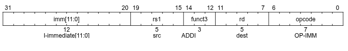
In the schematic, the most significant bits are on the left and the least significant bits on the right. The funct7, funct3, and opcode fields are just constants -- the bits in the corresponding places need to have a certain, fixed value. These values are listed in the instruction set listings in chapter 35, where we can see that for the ADDI instruction:
funct3has the value000opcodehas the value0010011
With that out of the way... Let's start coding.
We want the decoder only to try to decode when the is_active flag is set.
|
@@ -21,7 +21,11 @@ begin
|
|
| 21 |
process (clk)
|
| 22 |
begin
|
| 23 |
if rising_edge(clk) then
|
| 24 |
-
|
|
|
|
|
|
|
|
|
|
|
|
|
| 25 |
end if;
|
| 26 |
end process;
|
| 27 |
|
|
|
|
| 21 |
process (clk)
|
| 22 |
begin
|
| 23 |
if rising_edge(clk) then
|
| 24 |
+
if input.is_active = '1' then
|
| 25 |
+
-- TODO: decode instructions
|
| 26 |
+
else
|
| 27 |
+
output <= DEFAULT_DECODE_OUTPUT;
|
| 28 |
+
end if;
|
| 29 |
end if;
|
| 30 |
end process;
|
| 31 |
|
Let's start with recognizing the ADDI instruction by checking the values of the funct3, and opcode fields. Since many other opcodes use the same fields, I'll add variables for them, so that they can be re-used.
|
@@ -19,10 +19,22 @@ architecture rtl of decode is
|
|
| 19 |
begin
|
| 20 |
|
| 21 |
process (clk)
|
|
|
|
|
|
|
|
|
|
| 22 |
begin
|
| 23 |
if rising_edge(clk) then
|
|
|
|
|
|
|
|
|
|
|
|
|
|
|
|
|
|
|
| 24 |
if input.is_active = '1' then
|
| 25 |
-
|
|
|
|
|
|
|
|
|
|
| 26 |
else
|
| 27 |
output <= DEFAULT_DECODE_OUTPUT;
|
| 28 |
end if;
|
|
|
|
| 19 |
begin
|
| 20 |
|
| 21 |
process (clk)
|
| 22 |
+
variable opcode: std_logic_vector(6 downto 0);
|
| 23 |
+
variable funct3: std_logic_vector(2 downto 0);
|
| 24 |
+
variable rs1, rs2, rd : std_logic_vector(4 downto 0);
|
| 25 |
begin
|
| 26 |
if rising_edge(clk) then
|
| 27 |
+
opcode := input.instr(6 downto 0);
|
| 28 |
+
rs1 := input.instr(19 downto 15);
|
| 29 |
+
rs2 := input.instr(24 downto 20);
|
| 30 |
+
funct3 := input.instr(14 downto 12);
|
| 31 |
+
rd := input.instr(11 downto 7);
|
| 32 |
+
|
| 33 |
if input.is_active = '1' then
|
| 34 |
+
if opcode = "0010011" and funct3 = "000" then
|
| 35 |
+
-- ADDI rd, rs, imm (I-type): sets rd to the sum of rs1 and the sign-extended immediate
|
| 36 |
+
-- TODO: set control signals
|
| 37 |
+
end if;
|
| 38 |
else
|
| 39 |
output <= DEFAULT_DECODE_OUTPUT;
|
| 40 |
end if;
|
Now, if we recognize the ADDI instruction, we want to set the control signals, so we need to define some types and constants for them in the output type.
|
@@ -11,7 +11,9 @@ package core_constants is
|
|
| 11 |
);
|
| 12 |
|
| 13 |
constant DEFAULT_DECODE_OUTPUT: decode_output_t := (
|
| 14 |
-
|
|
|
|
|
|
|
| 15 |
);
|
| 16 |
|
| 17 |
constant DEFAULT_EXECUTE_OUTPUT: execute_output_t := (
|
|
|
|
| 11 |
);
|
| 12 |
|
| 13 |
constant DEFAULT_DECODE_OUTPUT: decode_output_t := (
|
| 14 |
+
operand1 => (others => '0'),
|
| 15 |
+
operand2 => (others => '0'),
|
| 16 |
+
destination_reg => (others => '0')
|
| 17 |
);
|
| 18 |
|
| 19 |
constant DEFAULT_EXECUTE_OUTPUT: execute_output_t := (
|
|
@@ -9,7 +9,9 @@ package core_types is
|
|
| 9 |
end record fetch_output_t;
|
| 10 |
|
| 11 |
type decode_output_t is record
|
| 12 |
-
|
|
|
|
|
|
|
| 13 |
end record decode_output_t;
|
| 14 |
|
| 15 |
type execute_output_t is record
|
|
|
|
| 9 |
end record fetch_output_t;
|
| 10 |
|
| 11 |
type decode_output_t is record
|
| 12 |
+
operand1: std_logic_vector(31 downto 0);
|
| 13 |
+
operand2: std_logic_vector(31 downto 0);
|
| 14 |
+
destination_reg: std_logic_vector(4 downto 0);
|
| 15 |
end record decode_output_t;
|
| 16 |
|
| 17 |
type execute_output_t is record
|
We'll define an enumeration type for the operation that the execute stage has to perform. For now, it will know a single operation, OP_ADD. We don't really need a "no operation" (NOP) value, the execute stage can just add the operands and not use the result, and it will be functionally the same as executing a NOP.
|
@@ -11,6 +11,7 @@ package core_constants is
|
|
| 11 |
);
|
| 12 |
|
| 13 |
constant DEFAULT_DECODE_OUTPUT: decode_output_t := (
|
|
|
|
| 14 |
operand1 => (others => '0'),
|
| 15 |
operand2 => (others => '0'),
|
| 16 |
destination_reg => (others => '0')
|
|
|
|
| 11 |
);
|
| 12 |
|
| 13 |
constant DEFAULT_DECODE_OUTPUT: decode_output_t := (
|
| 14 |
+
operation => OP_ADD,
|
| 15 |
operand1 => (others => '0'),
|
| 16 |
operand2 => (others => '0'),
|
| 17 |
destination_reg => (others => '0')
|
|
@@ -3,12 +3,15 @@ use ieee.std_logic_1164.all;
|
|
| 3 |
|
| 4 |
|
| 5 |
package core_types is
|
|
|
|
|
|
|
| 6 |
type fetch_output_t is record
|
| 7 |
is_active: std_logic;
|
| 8 |
instr: std_logic_vector(31 downto 0);
|
| 9 |
end record fetch_output_t;
|
| 10 |
|
| 11 |
type decode_output_t is record
|
|
|
|
| 12 |
operand1: std_logic_vector(31 downto 0);
|
| 13 |
operand2: std_logic_vector(31 downto 0);
|
| 14 |
destination_reg: std_logic_vector(4 downto 0);
|
|
|
|
| 3 |
|
| 4 |
|
| 5 |
package core_types is
|
| 6 |
+
type operation_t is (OP_ADD);
|
| 7 |
+
|
| 8 |
type fetch_output_t is record
|
| 9 |
is_active: std_logic;
|
| 10 |
instr: std_logic_vector(31 downto 0);
|
| 11 |
end record fetch_output_t;
|
| 12 |
|
| 13 |
type decode_output_t is record
|
| 14 |
+
operation: operation_t;
|
| 15 |
operand1: std_logic_vector(31 downto 0);
|
| 16 |
operand2: std_logic_vector(31 downto 0);
|
| 17 |
destination_reg: std_logic_vector(4 downto 0);
|
Now, we can finally set the output.
|
@@ -22,6 +22,9 @@ begin
|
|
| 22 |
variable opcode: std_logic_vector(6 downto 0);
|
| 23 |
variable funct3: std_logic_vector(2 downto 0);
|
| 24 |
variable rs1, rs2, rd : std_logic_vector(4 downto 0);
|
|
|
|
|
|
|
|
|
|
| 25 |
begin
|
| 26 |
if rising_edge(clk) then
|
| 27 |
opcode := input.instr(6 downto 0);
|
|
@@ -30,10 +33,16 @@ begin
|
|
| 30 |
funct3 := input.instr(14 downto 12);
|
| 31 |
rd := input.instr(11 downto 7);
|
| 32 |
|
|
|
|
|
|
|
|
|
|
| 33 |
if input.is_active = '1' then
|
| 34 |
if opcode = "0010011" and funct3 = "000" then
|
| 35 |
-- ADDI rd, rs, imm (I-type): sets rd to the sum of rs1 and the sign-extended immediate
|
| 36 |
-
|
|
|
|
|
|
|
|
|
|
| 37 |
end if;
|
| 38 |
else
|
| 39 |
output <= DEFAULT_DECODE_OUTPUT;
|
|
|
|
| 22 |
variable opcode: std_logic_vector(6 downto 0);
|
| 23 |
variable funct3: std_logic_vector(2 downto 0);
|
| 24 |
variable rs1, rs2, rd : std_logic_vector(4 downto 0);
|
| 25 |
+
|
| 26 |
+
variable i_imm: std_logic_vector(11 downto 0);
|
| 27 |
+
variable i_imm_s: std_logic_vector(31 downto 0);
|
| 28 |
begin
|
| 29 |
if rising_edge(clk) then
|
| 30 |
opcode := input.instr(6 downto 0);
|
|
|
|
| 33 |
funct3 := input.instr(14 downto 12);
|
| 34 |
rd := input.instr(11 downto 7);
|
| 35 |
|
| 36 |
+
i_imm := input.instr(31 downto 20);
|
| 37 |
+
i_imm_s := std_logic_vector(resize(signed(i_imm), 32));
|
| 38 |
+
|
| 39 |
if input.is_active = '1' then
|
| 40 |
if opcode = "0010011" and funct3 = "000" then
|
| 41 |
-- ADDI rd, rs, imm (I-type): sets rd to the sum of rs1 and the sign-extended immediate
|
| 42 |
+
output.operation <= OP_ADD;
|
| 43 |
+
output.operand1 <= (others => '0'); -- TODO: load value from register
|
| 44 |
+
output.operand2 <= i_imm_s;
|
| 45 |
+
output.destination_reg <= rd;
|
| 46 |
end if;
|
| 47 |
else
|
| 48 |
output <= DEFAULT_DECODE_OUTPUT;
|
Hmm, we still need to load values from registers. Normally you'd do this in a dedicated register file, but I will just define the registers here in the decode stage. If this will lead to any problems later on, we'll just deal with them at that point.
|
@@ -16,6 +16,9 @@ end decode;
|
|
| 16 |
|
| 17 |
|
| 18 |
architecture rtl of decode is
|
|
|
|
|
|
|
|
|
|
| 19 |
begin
|
| 20 |
|
| 21 |
process (clk)
|
|
|
|
| 16 |
|
| 17 |
|
| 18 |
architecture rtl of decode is
|
| 19 |
+
type registers is array(0 to 31) of std_logic_vector(31 downto 0);
|
| 20 |
+
signal reg: registers := (others => (others => '0'));
|
| 21 |
+
|
| 22 |
begin
|
| 23 |
|
| 24 |
process (clk)
|
Now, we can actually read the value from the registers when we set the output.
|
@@ -43,7 +43,7 @@ begin
|
|
| 43 |
if opcode = "0010011" and funct3 = "000" then
|
| 44 |
-- ADDI rd, rs, imm (I-type): sets rd to the sum of rs1 and the sign-extended immediate
|
| 45 |
output.operation <= OP_ADD;
|
| 46 |
-
output.operand1 <= (
|
| 47 |
output.operand2 <= i_imm_s;
|
| 48 |
output.destination_reg <= rd;
|
| 49 |
end if;
|
|
|
|
| 43 |
if opcode = "0010011" and funct3 = "000" then
|
| 44 |
-- ADDI rd, rs, imm (I-type): sets rd to the sum of rs1 and the sign-extended immediate
|
| 45 |
output.operation <= OP_ADD;
|
| 46 |
+
output.operand1 <= reg(to_integer(unsigned(rs1)));
|
| 47 |
output.operand2 <= i_imm_s;
|
| 48 |
output.destination_reg <= rd;
|
| 49 |
end if;
|
At this point the simulation is working, but does nothing. We'd like to execute the ADDI instruction. It's a good exercise to try to write the instruction bits of a simple ADDI instruction by hand. Let's do ADDI x1, x2, 123.
In the instruction set listing in the RISC-V documentation, we can find all the fields in the encoding for the ADDI instruction. In order from left to right (so most signficant to least significant bits), they are:
- The immediate field, which we set to
123, or, written as a 12-bit binary number,000001111011 - The
rs1field (the number of the register of the first operand), which will be2for thex2register, or00010as a 5-bit binary number - The
funct3field, which is000forADDI - The
rdfield, which is1for thex1register, or00001as a 5-bit binary number - The
opcodefield, which is0010011forADDI
Concatenating all the bits we get 00000111101100010000000010010011. Counting the bits, we see that indeed, we have 32 bits as expected. If we write this in hex, which is a more commonly used format for instruction code, we get 7b10093.
Indeed, if I enter addi x1, x0, 123 in this online RISC-V assembler, it returns 07b10093.
Now, we replace the first opcode by this value for testing.
|
@@ -17,7 +17,7 @@ end fetch;
|
|
| 17 |
architecture rtl of fetch is
|
| 18 |
type instruction_memory_t is array(0 to 15) of std_logic_vector(31 downto 0);
|
| 19 |
signal imem: instruction_memory_t := (
|
| 20 |
-
X"
|
| 21 |
X"00000009", X"0000000A", X"0000000B", X"0000000C", X"0000000D", X"0000000E", X"0000000F", X"00000010"
|
| 22 |
);
|
| 23 |
|
|
|
|
| 17 |
architecture rtl of fetch is
|
| 18 |
type instruction_memory_t is array(0 to 15) of std_logic_vector(31 downto 0);
|
| 19 |
signal imem: instruction_memory_t := (
|
| 20 |
+
X"07b10093", X"00000002", X"00000003", X"00000004", X"00000005", X"00000006", X"00000007", X"00000008",
|
| 21 |
X"00000009", X"0000000A", X"0000000B", X"0000000C", X"0000000D", X"0000000E", X"0000000F", X"00000010"
|
| 22 |
);
|
| 23 |
|
Now, we run the simulation for 50 ns and observe the inputs and outputs of the decode stage to verify everything is working as expected.
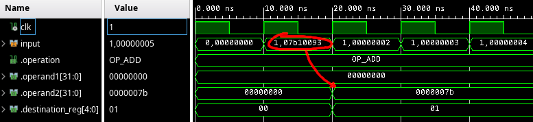
Now, we can see that in the second cycle, the ADDI x1, x2, 123 instruction we enters the decode stage. The next cycle, we see that the destination register is set to 1, indicating that the result of the operation should be written to x1. The second operand is also set to 7b, which is the hex encoding of 123. The first operand is set to 0, which is correct, since all registers are initialized to zero. It's a bit hard to verify that this comes from the correct register, but I'll trust this for now.
The cycle after that, we expect the output of the decode stage to be the same as the output before the ADDI instruction was decoded. However, the output stays the same, as if there was another, identical ADDI instruction right after the one we put.
So, we need to handle the case where no instruction is recognized in the decoder. In this case, I want to set the output to the default output. I also want to have an is_active flag like we have in the output of the fetch stage.
|
@@ -11,6 +11,7 @@ package core_constants is
|
|
| 11 |
);
|
| 12 |
|
| 13 |
constant DEFAULT_DECODE_OUTPUT: decode_output_t := (
|
|
|
|
| 14 |
operation => OP_ADD,
|
| 15 |
operand1 => (others => '0'),
|
| 16 |
operand2 => (others => '0'),
|
|
|
|
| 11 |
);
|
| 12 |
|
| 13 |
constant DEFAULT_DECODE_OUTPUT: decode_output_t := (
|
| 14 |
+
is_active => '0',
|
| 15 |
operation => OP_ADD,
|
| 16 |
operand1 => (others => '0'),
|
| 17 |
operand2 => (others => '0'),
|
|
@@ -40,6 +40,8 @@ begin
|
|
| 40 |
i_imm_s := std_logic_vector(resize(signed(i_imm), 32));
|
| 41 |
|
| 42 |
if input.is_active = '1' then
|
|
|
|
|
|
|
| 43 |
if opcode = "0010011" and funct3 = "000" then
|
| 44 |
-- ADDI rd, rs, imm (I-type): sets rd to the sum of rs1 and the sign-extended immediate
|
| 45 |
output.operation <= OP_ADD;
|
|
|
|
| 40 |
i_imm_s := std_logic_vector(resize(signed(i_imm), 32));
|
| 41 |
|
| 42 |
if input.is_active = '1' then
|
| 43 |
+
output.is_active <= '1';
|
| 44 |
+
|
| 45 |
if opcode = "0010011" and funct3 = "000" then
|
| 46 |
-- ADDI rd, rs, imm (I-type): sets rd to the sum of rs1 and the sign-extended immediate
|
| 47 |
output.operation <= OP_ADD;
|
|
@@ -11,6 +11,7 @@ package core_types is
|
|
| 11 |
end record fetch_output_t;
|
| 12 |
|
| 13 |
type decode_output_t is record
|
|
|
|
| 14 |
operation: operation_t;
|
| 15 |
operand1: std_logic_vector(31 downto 0);
|
| 16 |
operand2: std_logic_vector(31 downto 0);
|
|
|
|
| 11 |
end record fetch_output_t;
|
| 12 |
|
| 13 |
type decode_output_t is record
|
| 14 |
+
is_active: std_logic;
|
| 15 |
operation: operation_t;
|
| 16 |
operand1: std_logic_vector(31 downto 0);
|
| 17 |
operand2: std_logic_vector(31 downto 0);
|
Another problem is that we can't distinguish between "there was no instruction" and "the instruction could not be decoded". For this, I'd also like a flag to indicate when the decoder failed to decode an instruction. In this case, we'll interpret the instruction as an invalid instruction. Of course, until we have implemented decoding for all the RISC-V instructions, the instructions for which an implementation is missing will get tagged as invalid.
|
@@ -12,6 +12,7 @@ package core_constants is
|
|
| 12 |
|
| 13 |
constant DEFAULT_DECODE_OUTPUT: decode_output_t := (
|
| 14 |
is_active => '0',
|
|
|
|
| 15 |
operation => OP_ADD,
|
| 16 |
operand1 => (others => '0'),
|
| 17 |
operand2 => (others => '0'),
|
|
|
|
| 12 |
|
| 13 |
constant DEFAULT_DECODE_OUTPUT: decode_output_t := (
|
| 14 |
is_active => '0',
|
| 15 |
+
is_invalid => '0',
|
| 16 |
operation => OP_ADD,
|
| 17 |
operand1 => (others => '0'),
|
| 18 |
operand2 => (others => '0'),
|
|
@@ -28,6 +28,8 @@ begin
|
|
| 28 |
|
| 29 |
variable i_imm: std_logic_vector(11 downto 0);
|
| 30 |
variable i_imm_s: std_logic_vector(31 downto 0);
|
|
|
|
|
|
|
| 31 |
begin
|
| 32 |
if rising_edge(clk) then
|
| 33 |
opcode := input.instr(6 downto 0);
|
|
@@ -39,19 +41,26 @@ begin
|
|
| 39 |
i_imm := input.instr(31 downto 20);
|
| 40 |
i_imm_s := std_logic_vector(resize(signed(i_imm), 32));
|
| 41 |
|
|
|
|
|
|
|
| 42 |
if input.is_active = '1' then
|
| 43 |
-
|
|
|
|
| 44 |
|
| 45 |
if opcode = "0010011" and funct3 = "000" then
|
| 46 |
-- ADDI rd, rs, imm (I-type): sets rd to the sum of rs1 and the sign-extended immediate
|
| 47 |
-
|
| 48 |
-
|
| 49 |
-
|
| 50 |
-
|
|
|
|
|
|
|
| 51 |
end if;
|
| 52 |
else
|
| 53 |
output <= DEFAULT_DECODE_OUTPUT;
|
| 54 |
end if;
|
|
|
|
|
|
|
| 55 |
end if;
|
| 56 |
end process;
|
| 57 |
|
|
|
|
| 28 |
|
| 29 |
variable i_imm: std_logic_vector(11 downto 0);
|
| 30 |
variable i_imm_s: std_logic_vector(31 downto 0);
|
| 31 |
+
|
| 32 |
+
variable v_output: decode_output_t;
|
| 33 |
begin
|
| 34 |
if rising_edge(clk) then
|
| 35 |
opcode := input.instr(6 downto 0);
|
|
|
|
| 41 |
i_imm := input.instr(31 downto 20);
|
| 42 |
i_imm_s := std_logic_vector(resize(signed(i_imm), 32));
|
| 43 |
|
| 44 |
+
v_output := DEFAULT_DECODE_OUTPUT;
|
| 45 |
+
|
| 46 |
if input.is_active = '1' then
|
| 47 |
+
v_output.is_active := '1';
|
| 48 |
+
v_output.is_invalid := '0';
|
| 49 |
|
| 50 |
if opcode = "0010011" and funct3 = "000" then
|
| 51 |
-- ADDI rd, rs, imm (I-type): sets rd to the sum of rs1 and the sign-extended immediate
|
| 52 |
+
v_output.operation := OP_ADD;
|
| 53 |
+
v_output.operand1 := reg(to_integer(unsigned(rs1)));
|
| 54 |
+
v_output.operand2 := i_imm_s;
|
| 55 |
+
v_output.destination_reg := rd;
|
| 56 |
+
else
|
| 57 |
+
v_output.is_invalid := '1';
|
| 58 |
end if;
|
| 59 |
else
|
| 60 |
output <= DEFAULT_DECODE_OUTPUT;
|
| 61 |
end if;
|
| 62 |
+
|
| 63 |
+
output <= v_output;
|
| 64 |
end if;
|
| 65 |
end process;
|
| 66 |
|
|
@@ -12,6 +12,7 @@ package core_types is
|
|
| 12 |
|
| 13 |
type decode_output_t is record
|
| 14 |
is_active: std_logic;
|
|
|
|
| 15 |
operation: operation_t;
|
| 16 |
operand1: std_logic_vector(31 downto 0);
|
| 17 |
operand2: std_logic_vector(31 downto 0);
|
|
|
|
| 12 |
|
| 13 |
type decode_output_t is record
|
| 14 |
is_active: std_logic;
|
| 15 |
+
is_invalid: std_logic;
|
| 16 |
operation: operation_t;
|
| 17 |
operand1: std_logic_vector(31 downto 0);
|
| 18 |
operand2: std_logic_vector(31 downto 0);
|
I refactored the code slightly to use a variable, so that we can use DEFAULT_DECODE_OUTPUT by default and can overwrite individual fields of the output. This is not allowed for signals.
When we simulate again, the waveforms look like this.
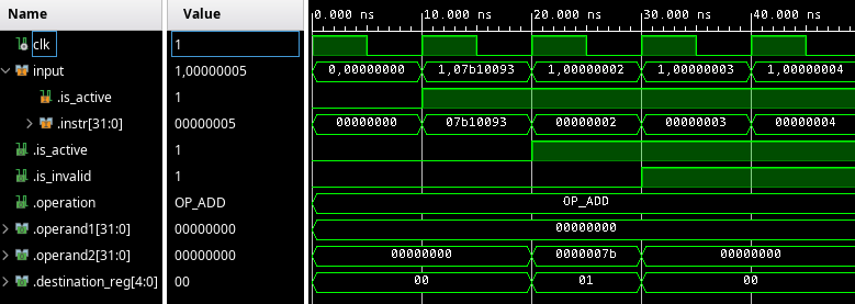
This is good; the first cycle and second cycle we see the output is not active (because the decode stage has not received any "active" output from the fetch stage yet). The third cycle we see that the decode output is active and valid and the operands as well as the operation and the destination register are correct. The cycles after that, the is_invalid flag is set, which is correct because the other instructions are still the values that count up, which are not correct instructions.
Now, decoding the other arithmetic instructions will be relatively straightforward. But first, we will focus on the rest of the stages, so that we can actually see our implementation of the ADDI instruction work.