This lesson starts at commit d20e09da83bc7dac0d753d0a4db9a9ce99c50327.
4. Execute and writeback stage
To recap, we have
- A fetch stage (which is a temporary hack that should be re-done, but for now it allows us to keep making progress).
- A decode stage, which only decodes the
ADDIinstruction.
The goal for this lesson is to actually execute the ADDI instruction and write the result back to the target register. Naturally, this requires changes to the execute and writeback stages.
From the execute stage, we want to return the result from the operation, and the destination register.
|
@@ -20,7 +20,8 @@ package core_constants is
|
|
| 20 |
);
|
| 21 |
|
| 22 |
constant DEFAULT_EXECUTE_OUTPUT: execute_output_t := (
|
| 23 |
-
|
|
|
|
| 24 |
);
|
| 25 |
|
| 26 |
constant DEFAULT_MEMORY_OUTPUT: memory_output_t := (
|
|
|
|
| 20 |
);
|
| 21 |
|
| 22 |
constant DEFAULT_EXECUTE_OUTPUT: execute_output_t := (
|
| 23 |
+
result => (others => '0'),
|
| 24 |
+
destination_reg => (others => '0')
|
| 25 |
);
|
| 26 |
|
| 27 |
constant DEFAULT_MEMORY_OUTPUT: memory_output_t := (
|
|
@@ -20,7 +20,8 @@ package core_types is
|
|
| 20 |
end record decode_output_t;
|
| 21 |
|
| 22 |
type execute_output_t is record
|
| 23 |
-
|
|
|
|
| 24 |
end record execute_output_t;
|
| 25 |
|
| 26 |
type memory_output_t is record
|
|
|
|
| 20 |
end record decode_output_t;
|
| 21 |
|
| 22 |
type execute_output_t is record
|
| 23 |
+
result: std_logic_vector(31 downto 0);
|
| 24 |
+
destination_reg: std_logic_vector(4 downto 0);
|
| 25 |
end record execute_output_t;
|
| 26 |
|
| 27 |
type memory_output_t is record
|
We want to pass this on to the writeback stage, but the memory stage is inbetween, still. We'll adapt the memory stage to just copy the input.
|
@@ -25,6 +25,7 @@ package core_constants is
|
|
| 25 |
);
|
| 26 |
|
| 27 |
constant DEFAULT_MEMORY_OUTPUT: memory_output_t := (
|
| 28 |
-
|
|
|
|
| 29 |
);
|
| 30 |
end package core_constants;
|
|
|
|
| 25 |
);
|
| 26 |
|
| 27 |
constant DEFAULT_MEMORY_OUTPUT: memory_output_t := (
|
| 28 |
+
result => (others => '0'),
|
| 29 |
+
destination_reg => (others => '0')
|
| 30 |
);
|
| 31 |
end package core_constants;
|
|
@@ -21,7 +21,8 @@ begin
|
|
| 21 |
process (clk)
|
| 22 |
begin
|
| 23 |
if rising_edge(clk) then
|
| 24 |
-
|
|
|
|
| 25 |
end if;
|
| 26 |
end process;
|
| 27 |
|
|
|
|
| 21 |
process (clk)
|
| 22 |
begin
|
| 23 |
if rising_edge(clk) then
|
| 24 |
+
output.result <= input.result;
|
| 25 |
+
output.destination_reg <= input.destination_reg;
|
| 26 |
end if;
|
| 27 |
end process;
|
| 28 |
|
|
@@ -25,6 +25,7 @@ package core_types is
|
|
| 25 |
end record execute_output_t;
|
| 26 |
|
| 27 |
type memory_output_t is record
|
| 28 |
-
|
|
|
|
| 29 |
end record memory_output_t;
|
| 30 |
end package core_types;
|
|
|
|
| 25 |
end record execute_output_t;
|
| 26 |
|
| 27 |
type memory_output_t is record
|
| 28 |
+
result: std_logic_vector(31 downto 0);
|
| 29 |
+
destination_reg: std_logic_vector(4 downto 0);
|
| 30 |
end record memory_output_t;
|
| 31 |
end package core_types;
|
Now, we still need to provide the actual implementations in the execute and writeback stage.
In the execute stage, we want to ignore inactive signals and invalid instructions (we will need to handle invalid instructions some day, but today is not that day). For invalid or inactive instructions we'll simply output the default output. To signal "we don't need to write to a register", we simply set the destination register to 0, because in RISC-V the first register, x0, always holds zero, and it cannot be overwritten. We'll need to handle this in the writeback stage.
|
@@ -21,7 +21,12 @@ begin
|
|
| 21 |
process (clk)
|
| 22 |
begin
|
| 23 |
if rising_edge(clk) then
|
| 24 |
-
|
|
|
|
|
|
|
|
|
|
|
|
|
|
|
|
| 25 |
end if;
|
| 26 |
end process;
|
| 27 |
|
|
|
|
| 21 |
process (clk)
|
| 22 |
begin
|
| 23 |
if rising_edge(clk) then
|
| 24 |
+
if input.is_active = '1' and input.is_invalid = '0' then
|
| 25 |
+
output.result <= (others => '0'); -- TODO: fill this with the result from the operation
|
| 26 |
+
output.destination_reg <= input.destination_reg;
|
| 27 |
+
else
|
| 28 |
+
output <= DEFAULT_EXECUTE_OUTPUT;
|
| 29 |
+
end if;
|
| 30 |
end if;
|
| 31 |
end process;
|
| 32 |
|
Now, we're ready to actually handle the addition operation in the execute stage.
|
@@ -22,7 +22,12 @@ begin
|
|
| 22 |
begin
|
| 23 |
if rising_edge(clk) then
|
| 24 |
if input.is_active = '1' and input.is_invalid = '0' then
|
| 25 |
-
|
|
|
|
|
|
|
|
|
|
|
|
|
|
|
|
| 26 |
output.destination_reg <= input.destination_reg;
|
| 27 |
else
|
| 28 |
output <= DEFAULT_EXECUTE_OUTPUT;
|
|
|
|
| 22 |
begin
|
| 23 |
if rising_edge(clk) then
|
| 24 |
if input.is_active = '1' and input.is_invalid = '0' then
|
| 25 |
+
if input.operation = OP_ADD then
|
| 26 |
+
output.result <= std_logic_vector(unsigned(input.operand1) + unsigned(input.operand2));
|
| 27 |
+
else
|
| 28 |
+
-- this should never happen
|
| 29 |
+
end if;
|
| 30 |
+
|
| 31 |
output.destination_reg <= input.destination_reg;
|
| 32 |
else
|
| 33 |
output <= DEFAULT_EXECUTE_OUTPUT;
|
We can make the "this should never happen" a bit more robust by making it an assertion.
|
@@ -25,7 +25,7 @@ begin
|
|
| 25 |
if input.operation = OP_ADD then
|
| 26 |
output.result <= std_logic_vector(unsigned(input.operand1) + unsigned(input.operand2));
|
| 27 |
else
|
| 28 |
-
|
| 29 |
end if;
|
| 30 |
|
| 31 |
output.destination_reg <= input.destination_reg;
|
|
|
|
| 25 |
if input.operation = OP_ADD then
|
| 26 |
output.result <= std_logic_vector(unsigned(input.operand1) + unsigned(input.operand2));
|
| 27 |
else
|
| 28 |
+
assert false report "Unhandled operation value in execute stage" severity failure;
|
| 29 |
end if;
|
| 30 |
|
| 31 |
output.destination_reg <= input.destination_reg;
|
If we test this in simulation, we see the correct values for result and destination_reg show up in the writeback stage.
However, the writeback stage itself doesn't do anything. We run into a problem here; In the last lesson we put the registers in the decode stage, so we don't have access to them from the write stage...
Like I mentioned last time, one solution is to make a module for a register file, that the decode stage and the writeback stage can both talk to. However, I don't really like making an additional module, and instead I'll opt to merge the writeback stage and the decode stage into a single module, which I'll simply call decode_write. I will adapt the decode module and delete the write module (which was only a placeholder anyway).
So, the core module will need to route the output of the memory stage back to the decode stage, which will then handle writing the final value to the destination register.
First, I'll rename decode.vhd to decode_write.vhd and delete write.vhd.
|
@@ -1,27 +0,0 @@
|
|
| 1 |
-
library ieee;
|
| 2 |
-
use ieee.std_logic_1164.all;
|
| 3 |
-
use ieee.numeric_std.all;
|
| 4 |
-
|
| 5 |
-
use work.core_types.all;
|
| 6 |
-
use work.core_constants.all;
|
| 7 |
-
|
| 8 |
-
|
| 9 |
-
entity write is
|
| 10 |
-
port (
|
| 11 |
-
clk: in std_logic;
|
| 12 |
-
input: in memory_output_t
|
| 13 |
-
);
|
| 14 |
-
end write;
|
| 15 |
-
|
| 16 |
-
|
| 17 |
-
architecture rtl of write is
|
| 18 |
-
begin
|
| 19 |
-
|
| 20 |
-
process (clk)
|
| 21 |
-
begin
|
| 22 |
-
if rising_edge(clk) then
|
| 23 |
-
-- TODO: implement
|
| 24 |
-
end if;
|
| 25 |
-
end process;
|
| 26 |
-
|
| 27 |
-
end rtl;
|
|
|
|
|
|
|
|
|
|
|
|
|
|
|
|
|
|
|
|
|
|
|
|
|
|
|
|
|
|
|
|
|
|
|
|
|
|
|
|
|
|
|
|
|
|
|
|
|
|
|
|
|
|
|
|
|
|
|
|
|
|
|
|
|
|
|
|
|
|
|
|
|
|
|
|
|
|
|
|
|
|
|
|
Then, I'll make the decode_write module take the output from the memory stage.
|
@@ -26,11 +26,12 @@ architecture rtl of core is
|
|
| 26 |
);
|
| 27 |
end component;
|
| 28 |
|
| 29 |
-
component
|
| 30 |
port (
|
| 31 |
clk: in std_logic;
|
| 32 |
-
|
| 33 |
-
|
|
|
|
| 34 |
);
|
| 35 |
end component;
|
| 36 |
|
|
@@ -50,22 +51,13 @@ architecture rtl of core is
|
|
| 50 |
);
|
| 51 |
end component;
|
| 52 |
|
| 53 |
-
component write is
|
| 54 |
-
port (
|
| 55 |
-
clk: in std_logic;
|
| 56 |
-
input: in memory_output_t
|
| 57 |
-
);
|
| 58 |
-
end component;
|
| 59 |
-
|
| 60 |
begin
|
| 61 |
fetch_inst: fetch port map(clk => clk, output => fetch_output);
|
| 62 |
|
| 63 |
-
|
| 64 |
|
| 65 |
execute_inst: execute port map(clk => clk, input => decode_output, output => execute_output);
|
| 66 |
|
| 67 |
memory_inst: memory port map(clk => clk, input => execute_output, output => memory_output);
|
| 68 |
|
| 69 |
-
write_inst: write port map(clk => clk, input => memory_output);
|
| 70 |
-
|
| 71 |
end rtl;
|
|
|
|
| 26 |
);
|
| 27 |
end component;
|
| 28 |
|
| 29 |
+
component decode_write is
|
| 30 |
port (
|
| 31 |
clk: in std_logic;
|
| 32 |
+
decode_input: in fetch_output_t;
|
| 33 |
+
decode_output: out decode_output_t;
|
| 34 |
+
write_input: in memory_output_t
|
| 35 |
);
|
| 36 |
end component;
|
| 37 |
|
|
|
|
| 51 |
);
|
| 52 |
end component;
|
| 53 |
|
|
|
|
|
|
|
|
|
|
|
|
|
|
|
|
|
|
|
|
|
|
| 54 |
begin
|
| 55 |
fetch_inst: fetch port map(clk => clk, output => fetch_output);
|
| 56 |
|
| 57 |
+
decode_write_inst: decode_write port map(clk => clk, decode_input => fetch_output, decode_output => decode_output, write_input => memory_output);
|
| 58 |
|
| 59 |
execute_inst: execute port map(clk => clk, input => decode_output, output => execute_output);
|
| 60 |
|
| 61 |
memory_inst: memory port map(clk => clk, input => execute_output, output => memory_output);
|
| 62 |
|
|
|
|
|
|
|
| 63 |
end rtl;
|
|
@@ -6,16 +6,19 @@ use work.core_types.all;
|
|
| 6 |
use work.core_constants.all;
|
| 7 |
|
| 8 |
|
| 9 |
-
entity
|
| 10 |
port (
|
| 11 |
clk: in std_logic;
|
| 12 |
-
|
| 13 |
-
|
|
|
|
|
|
|
|
|
|
| 14 |
);
|
| 15 |
-
end
|
| 16 |
|
| 17 |
|
| 18 |
-
architecture rtl of
|
| 19 |
type registers is array(0 to 31) of std_logic_vector(31 downto 0);
|
| 20 |
signal reg: registers := (others => (others => '0'));
|
| 21 |
|
|
@@ -29,38 +32,38 @@ begin
|
|
| 29 |
variable i_imm: std_logic_vector(11 downto 0);
|
| 30 |
variable i_imm_s: std_logic_vector(31 downto 0);
|
| 31 |
|
| 32 |
-
variable
|
| 33 |
begin
|
| 34 |
if rising_edge(clk) then
|
| 35 |
-
opcode :=
|
| 36 |
-
rs1 :=
|
| 37 |
-
rs2 :=
|
| 38 |
-
funct3 :=
|
| 39 |
-
rd :=
|
| 40 |
|
| 41 |
-
i_imm :=
|
| 42 |
i_imm_s := std_logic_vector(resize(signed(i_imm), 32));
|
| 43 |
|
| 44 |
-
|
| 45 |
|
| 46 |
-
if
|
| 47 |
-
|
| 48 |
-
|
| 49 |
|
| 50 |
if opcode = "0010011" and funct3 = "000" then
|
| 51 |
-- ADDI rd, rs, imm (I-type): sets rd to the sum of rs1 and the sign-extended immediate
|
| 52 |
-
|
| 53 |
-
|
| 54 |
-
|
| 55 |
-
|
| 56 |
else
|
| 57 |
-
|
| 58 |
end if;
|
| 59 |
else
|
| 60 |
-
|
| 61 |
end if;
|
| 62 |
|
| 63 |
-
|
| 64 |
end if;
|
| 65 |
end process;
|
| 66 |
|
|
|
|
| 6 |
use work.core_constants.all;
|
| 7 |
|
| 8 |
|
| 9 |
+
entity decode_write is
|
| 10 |
port (
|
| 11 |
clk: in std_logic;
|
| 12 |
+
|
| 13 |
+
decode_input: in fetch_output_t;
|
| 14 |
+
decode_output: out decode_output_t := DEFAULT_DECODE_OUTPUT;
|
| 15 |
+
|
| 16 |
+
write_input: in memory_output_t
|
| 17 |
);
|
| 18 |
+
end decode_write;
|
| 19 |
|
| 20 |
|
| 21 |
+
architecture rtl of decode_write is
|
| 22 |
type registers is array(0 to 31) of std_logic_vector(31 downto 0);
|
| 23 |
signal reg: registers := (others => (others => '0'));
|
| 24 |
|
|
|
|
| 32 |
variable i_imm: std_logic_vector(11 downto 0);
|
| 33 |
variable i_imm_s: std_logic_vector(31 downto 0);
|
| 34 |
|
| 35 |
+
variable v_decode_output: decode_output_t;
|
| 36 |
begin
|
| 37 |
if rising_edge(clk) then
|
| 38 |
+
opcode := decode_input.instr(6 downto 0);
|
| 39 |
+
rs1 := decode_input.instr(19 downto 15);
|
| 40 |
+
rs2 := decode_input.instr(24 downto 20);
|
| 41 |
+
funct3 := decode_input.instr(14 downto 12);
|
| 42 |
+
rd := decode_input.instr(11 downto 7);
|
| 43 |
|
| 44 |
+
i_imm := decode_input.instr(31 downto 20);
|
| 45 |
i_imm_s := std_logic_vector(resize(signed(i_imm), 32));
|
| 46 |
|
| 47 |
+
v_decode_output := DEFAULT_DECODE_OUTPUT;
|
| 48 |
|
| 49 |
+
if decode_input.is_active = '1' then
|
| 50 |
+
v_decode_output.is_active := '1';
|
| 51 |
+
v_decode_output.is_invalid := '0';
|
| 52 |
|
| 53 |
if opcode = "0010011" and funct3 = "000" then
|
| 54 |
-- ADDI rd, rs, imm (I-type): sets rd to the sum of rs1 and the sign-extended immediate
|
| 55 |
+
v_decode_output.operation := OP_ADD;
|
| 56 |
+
v_decode_output.operand1 := reg(to_integer(unsigned(rs1)));
|
| 57 |
+
v_decode_output.operand2 := i_imm_s;
|
| 58 |
+
v_decode_output.destination_reg := rd;
|
| 59 |
else
|
| 60 |
+
v_decode_output.is_invalid := '1';
|
| 61 |
end if;
|
| 62 |
else
|
| 63 |
+
decode_output <= DEFAULT_DECODE_OUTPUT;
|
| 64 |
end if;
|
| 65 |
|
| 66 |
+
decode_output <= v_decode_output;
|
| 67 |
end if;
|
| 68 |
end process;
|
| 69 |
|
Now, it's relatively easy to perform the write to the destination register.
|
@@ -35,6 +35,11 @@ begin
|
|
| 35 |
variable v_decode_output: decode_output_t;
|
| 36 |
begin
|
| 37 |
if rising_edge(clk) then
|
|
|
|
|
|
|
|
|
|
|
|
|
|
|
|
| 38 |
opcode := decode_input.instr(6 downto 0);
|
| 39 |
rs1 := decode_input.instr(19 downto 15);
|
| 40 |
rs2 := decode_input.instr(24 downto 20);
|
|
|
|
| 35 |
variable v_decode_output: decode_output_t;
|
| 36 |
begin
|
| 37 |
if rising_edge(clk) then
|
| 38 |
+
-- write back result if the destination register is not x0 (which always stays 0)
|
| 39 |
+
if write_input.destination_reg /= "00000" then
|
| 40 |
+
reg(to_integer(unsigned(write_input.destination_reg))) <= write_input.result;
|
| 41 |
+
end if;
|
| 42 |
+
|
| 43 |
opcode := decode_input.instr(6 downto 0);
|
| 44 |
rs1 := decode_input.instr(19 downto 15);
|
| 45 |
rs2 := decode_input.instr(24 downto 20);
|
If we simulate this for 70 ns and observer the input to the write stage and the x1 register, we see the following waveforms.
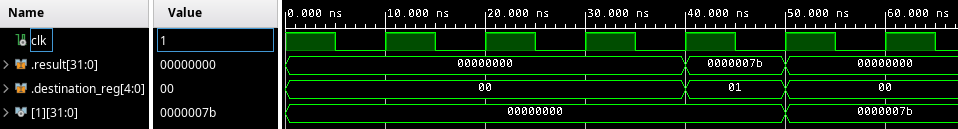
This looks good; The value 0x7b (which is 123 in hex) gets written to the x1 register. We have implemented our first RISC-V instruction, and it looks like it's being executed correctly! You can give yourself a pat on the back, this is a nice milestone!
When you're done celebrating, let's try another test case, that increments the x1 register twice in a row. That is, let's execute
ADDI x1, x1, 1
ADDI x1, x1, 1
Again using this sweet online RISC-V assembler, we see that ADDI x1, x1, 1 assembles to 00108093. We put this instruction in our instruction memory twice.
|
@@ -17,7 +17,7 @@ end fetch;
|
|
| 17 |
architecture rtl of fetch is
|
| 18 |
type instruction_memory_t is array(0 to 15) of std_logic_vector(31 downto 0);
|
| 19 |
signal imem: instruction_memory_t := (
|
| 20 |
-
X"
|
| 21 |
X"00000009", X"0000000A", X"0000000B", X"0000000C", X"0000000D", X"0000000E", X"0000000F", X"00000010"
|
| 22 |
);
|
| 23 |
|
|
|
|
| 17 |
architecture rtl of fetch is
|
| 18 |
type instruction_memory_t is array(0 to 15) of std_logic_vector(31 downto 0);
|
| 19 |
signal imem: instruction_memory_t := (
|
| 20 |
+
X"00108093", X"00108093", X"00000003", X"00000004", X"00000005", X"00000006", X"00000007", X"00000008",
|
| 21 |
X"00000009", X"0000000A", X"0000000B", X"0000000C", X"0000000D", X"0000000E", X"0000000F", X"00000010"
|
| 22 |
);
|
| 23 |
|
Now we run the simulation again for 70 ns, observing the input for the write stage, and the value of the x1 register.
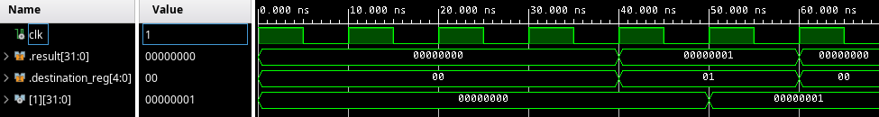
We can see that in the fifth and sixth cycle, a write to the x1 register happens (destination_reg is set to 1). However, the value of result, which is written to the register, should be 2 the second time. So, we have a bug.
What is going on? When the second ADDI x1, x1, 1 instruction arrives in the decode stage, the value of the x1 is read as 0, since the instruction before it has not yet finished executing.
This phenomenon where one instruction needs the result of an instruction before it that has not yet finished, is known as a read-after-write hazard. In pipelined processors, you need to track these dependencies, and wait until all the dependencies have finished executing. The cycles where the processor is waiting are called "pipeline bubbles" or "pipeline stalls". In our case, these manifest as cycles where the output of a stage has the is_active set to 0.
So the proper solution is to keep track of the number of instructions in the pipeline that write to every register. However, I don't feel like doing that at this point. Instead, I am going to do something much simpler for now: Let the fetch wait until the previous instruction has finished. This is potentially much slower than doing the proper solution, but I really want to get a simple processor working before spending a lot of effort to pipeline it.
So, what we can do is add an output pipeline_ready to the write stage, that will be set to 1 for a cycle whenever an active instruction finishes. This signal will then be fed back to the fetch stage, and a new instruction will only be fetched when this signal is 1.
For this, first we need to propagate the is_active signal all the way to the write stage.
|
@@ -20,11 +20,13 @@ package core_constants is
|
|
| 20 |
);
|
| 21 |
|
| 22 |
constant DEFAULT_EXECUTE_OUTPUT: execute_output_t := (
|
|
|
|
| 23 |
result => (others => '0'),
|
| 24 |
destination_reg => (others => '0')
|
| 25 |
);
|
| 26 |
|
| 27 |
constant DEFAULT_MEMORY_OUTPUT: memory_output_t := (
|
|
|
|
| 28 |
result => (others => '0'),
|
| 29 |
destination_reg => (others => '0')
|
| 30 |
);
|
|
|
|
| 20 |
);
|
| 21 |
|
| 22 |
constant DEFAULT_EXECUTE_OUTPUT: execute_output_t := (
|
| 23 |
+
is_active => '0',
|
| 24 |
result => (others => '0'),
|
| 25 |
destination_reg => (others => '0')
|
| 26 |
);
|
| 27 |
|
| 28 |
constant DEFAULT_MEMORY_OUTPUT: memory_output_t := (
|
| 29 |
+
is_active => '0',
|
| 30 |
result => (others => '0'),
|
| 31 |
destination_reg => (others => '0')
|
| 32 |
);
|
|
@@ -19,19 +19,23 @@ architecture rtl of execute is
|
|
| 19 |
begin
|
| 20 |
|
| 21 |
process (clk)
|
|
|
|
| 22 |
begin
|
| 23 |
if rising_edge(clk) then
|
|
|
|
|
|
|
|
|
|
| 24 |
if input.is_active = '1' and input.is_invalid = '0' then
|
| 25 |
if input.operation = OP_ADD then
|
| 26 |
-
|
| 27 |
else
|
| 28 |
assert false report "Unhandled operation value in execute stage" severity failure;
|
| 29 |
end if;
|
| 30 |
|
| 31 |
-
|
| 32 |
-
else
|
| 33 |
-
output <= DEFAULT_EXECUTE_OUTPUT;
|
| 34 |
end if;
|
|
|
|
|
|
|
| 35 |
end if;
|
| 36 |
end process;
|
| 37 |
|
|
|
|
| 19 |
begin
|
| 20 |
|
| 21 |
process (clk)
|
| 22 |
+
variable v_output: execute_output_t;
|
| 23 |
begin
|
| 24 |
if rising_edge(clk) then
|
| 25 |
+
v_output := DEFAULT_EXECUTE_OUTPUT;
|
| 26 |
+
v_output.is_active := input.is_active;
|
| 27 |
+
|
| 28 |
if input.is_active = '1' and input.is_invalid = '0' then
|
| 29 |
if input.operation = OP_ADD then
|
| 30 |
+
v_output.result := std_logic_vector(unsigned(input.operand1) + unsigned(input.operand2));
|
| 31 |
else
|
| 32 |
assert false report "Unhandled operation value in execute stage" severity failure;
|
| 33 |
end if;
|
| 34 |
|
| 35 |
+
v_output.destination_reg := input.destination_reg;
|
|
|
|
|
|
|
| 36 |
end if;
|
| 37 |
+
|
| 38 |
+
output <= v_output;
|
| 39 |
end if;
|
| 40 |
end process;
|
| 41 |
|
|
@@ -21,6 +21,7 @@ begin
|
|
| 21 |
process (clk)
|
| 22 |
begin
|
| 23 |
if rising_edge(clk) then
|
|
|
|
| 24 |
output.result <= input.result;
|
| 25 |
output.destination_reg <= input.destination_reg;
|
| 26 |
end if;
|
|
|
|
| 21 |
process (clk)
|
| 22 |
begin
|
| 23 |
if rising_edge(clk) then
|
| 24 |
+
output.is_active <= input.is_active;
|
| 25 |
output.result <= input.result;
|
| 26 |
output.destination_reg <= input.destination_reg;
|
| 27 |
end if;
|
|
@@ -20,11 +20,13 @@ package core_types is
|
|
| 20 |
end record decode_output_t;
|
| 21 |
|
| 22 |
type execute_output_t is record
|
|
|
|
| 23 |
result: std_logic_vector(31 downto 0);
|
| 24 |
destination_reg: std_logic_vector(4 downto 0);
|
| 25 |
end record execute_output_t;
|
| 26 |
|
| 27 |
type memory_output_t is record
|
|
|
|
| 28 |
result: std_logic_vector(31 downto 0);
|
| 29 |
destination_reg: std_logic_vector(4 downto 0);
|
| 30 |
end record memory_output_t;
|
|
|
|
| 20 |
end record decode_output_t;
|
| 21 |
|
| 22 |
type execute_output_t is record
|
| 23 |
+
is_active: std_logic;
|
| 24 |
result: std_logic_vector(31 downto 0);
|
| 25 |
destination_reg: std_logic_vector(4 downto 0);
|
| 26 |
end record execute_output_t;
|
| 27 |
|
| 28 |
type memory_output_t is record
|
| 29 |
+
is_active: std_logic;
|
| 30 |
result: std_logic_vector(31 downto 0);
|
| 31 |
destination_reg: std_logic_vector(4 downto 0);
|
| 32 |
end record memory_output_t;
|
With that done, we "loop" the signal back around as pipeline_ready from the write stage back to the fetch stage, and only fetch if it's 1. We initialize the value to 1 in the output of the write stage to not get in a "deadlock", with the pipeline waiting for an instruction, and the fetch unit waiting until an instruction finishes.
|
@@ -18,10 +18,12 @@ architecture rtl of core is
|
|
| 18 |
signal decode_output: decode_output_t;
|
| 19 |
signal execute_output: execute_output_t;
|
| 20 |
signal memory_output: memory_output_t;
|
|
|
|
| 21 |
|
| 22 |
component fetch is
|
| 23 |
port (
|
| 24 |
clk: in std_logic;
|
|
|
|
| 25 |
output: out fetch_output_t
|
| 26 |
);
|
| 27 |
end component;
|
|
@@ -31,7 +33,8 @@ architecture rtl of core is
|
|
| 31 |
clk: in std_logic;
|
| 32 |
decode_input: in fetch_output_t;
|
| 33 |
decode_output: out decode_output_t;
|
| 34 |
-
write_input: in memory_output_t
|
|
|
|
| 35 |
);
|
| 36 |
end component;
|
| 37 |
|
|
@@ -52,9 +55,9 @@ architecture rtl of core is
|
|
| 52 |
end component;
|
| 53 |
|
| 54 |
begin
|
| 55 |
-
fetch_inst: fetch port map(clk => clk, output => fetch_output);
|
| 56 |
|
| 57 |
-
decode_write_inst: decode_write port map(clk => clk, decode_input => fetch_output, decode_output => decode_output, write_input => memory_output);
|
| 58 |
|
| 59 |
execute_inst: execute port map(clk => clk, input => decode_output, output => execute_output);
|
| 60 |
|
|
|
|
| 18 |
signal decode_output: decode_output_t;
|
| 19 |
signal execute_output: execute_output_t;
|
| 20 |
signal memory_output: memory_output_t;
|
| 21 |
+
signal pipeline_ready: std_logic;
|
| 22 |
|
| 23 |
component fetch is
|
| 24 |
port (
|
| 25 |
clk: in std_logic;
|
| 26 |
+
pipeline_ready: in std_logic;
|
| 27 |
output: out fetch_output_t
|
| 28 |
);
|
| 29 |
end component;
|
|
|
|
| 33 |
clk: in std_logic;
|
| 34 |
decode_input: in fetch_output_t;
|
| 35 |
decode_output: out decode_output_t;
|
| 36 |
+
write_input: in memory_output_t;
|
| 37 |
+
pipeline_ready: out std_logic
|
| 38 |
);
|
| 39 |
end component;
|
| 40 |
|
|
|
|
| 55 |
end component;
|
| 56 |
|
| 57 |
begin
|
| 58 |
+
fetch_inst: fetch port map(clk => clk, output => fetch_output, pipeline_ready => pipeline_ready);
|
| 59 |
|
| 60 |
+
decode_write_inst: decode_write port map(clk => clk, decode_input => fetch_output, decode_output => decode_output, write_input => memory_output, pipeline_ready => pipeline_ready);
|
| 61 |
|
| 62 |
execute_inst: execute port map(clk => clk, input => decode_output, output => execute_output);
|
| 63 |
|
|
@@ -13,7 +13,8 @@ entity decode_write is
|
|
| 13 |
decode_input: in fetch_output_t;
|
| 14 |
decode_output: out decode_output_t := DEFAULT_DECODE_OUTPUT;
|
| 15 |
|
| 16 |
-
write_input: in memory_output_t
|
|
|
|
| 17 |
);
|
| 18 |
end decode_write;
|
| 19 |
|
|
@@ -40,6 +41,8 @@ begin
|
|
| 40 |
reg(to_integer(unsigned(write_input.destination_reg))) <= write_input.result;
|
| 41 |
end if;
|
| 42 |
|
|
|
|
|
|
|
| 43 |
opcode := decode_input.instr(6 downto 0);
|
| 44 |
rs1 := decode_input.instr(19 downto 15);
|
| 45 |
rs2 := decode_input.instr(24 downto 20);
|
|
|
|
| 13 |
decode_input: in fetch_output_t;
|
| 14 |
decode_output: out decode_output_t := DEFAULT_DECODE_OUTPUT;
|
| 15 |
|
| 16 |
+
write_input: in memory_output_t;
|
| 17 |
+
pipeline_ready: out std_logic := '1'
|
| 18 |
);
|
| 19 |
end decode_write;
|
| 20 |
|
|
|
|
| 41 |
reg(to_integer(unsigned(write_input.destination_reg))) <= write_input.result;
|
| 42 |
end if;
|
| 43 |
|
| 44 |
+
pipeline_ready <= write_input.is_active;
|
| 45 |
+
|
| 46 |
opcode := decode_input.instr(6 downto 0);
|
| 47 |
rs1 := decode_input.instr(19 downto 15);
|
| 48 |
rs2 := decode_input.instr(24 downto 20);
|
|
@@ -9,6 +9,7 @@ use work.core_constants.all;
|
|
| 9 |
entity fetch is
|
| 10 |
port (
|
| 11 |
clk: in std_logic;
|
|
|
|
| 12 |
output: out fetch_output_t := DEFAULT_FETCH_OUTPUT
|
| 13 |
);
|
| 14 |
end fetch;
|
|
@@ -28,10 +29,14 @@ begin
|
|
| 28 |
process (clk)
|
| 29 |
begin
|
| 30 |
if rising_edge(clk) then
|
| 31 |
-
|
| 32 |
-
|
| 33 |
-
|
| 34 |
-
|
|
|
|
|
|
|
|
|
|
|
|
|
| 35 |
end if;
|
| 36 |
end process;
|
| 37 |
|
|
|
|
| 9 |
entity fetch is
|
| 10 |
port (
|
| 11 |
clk: in std_logic;
|
| 12 |
+
pipeline_ready: in std_logic;
|
| 13 |
output: out fetch_output_t := DEFAULT_FETCH_OUTPUT
|
| 14 |
);
|
| 15 |
end fetch;
|
|
|
|
| 29 |
process (clk)
|
| 30 |
begin
|
| 31 |
if rising_edge(clk) then
|
| 32 |
+
if pipeline_ready = '1' then
|
| 33 |
+
pc <= pc + 4;
|
| 34 |
+
|
| 35 |
+
output.is_active <= '1';
|
| 36 |
+
output.instr <= imem(to_integer(pc(5 downto 2)));
|
| 37 |
+
else
|
| 38 |
+
output <= DEFAULT_FETCH_OUTPUT;
|
| 39 |
+
end if;
|
| 40 |
end if;
|
| 41 |
end process;
|
| 42 |
|
With this change, we see the value of x1 settles on 2, after 100 ns.
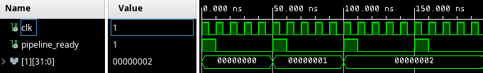
So, now we can also execute multiple successive ADDI instructions.
While we have only implemented a single instruction, it is worth realizing that implementing more instructions is relatively easy, since most of the "infrastructure" is there. To illustrate this, let's implement the ADD instruction, which is similar to ADDI but operates on two registers instead of a register and an immediate value.
|
@@ -28,6 +28,7 @@ begin
|
|
| 28 |
process (clk)
|
| 29 |
variable opcode: std_logic_vector(6 downto 0);
|
| 30 |
variable funct3: std_logic_vector(2 downto 0);
|
|
|
|
| 31 |
variable rs1, rs2, rd : std_logic_vector(4 downto 0);
|
| 32 |
|
| 33 |
variable i_imm: std_logic_vector(11 downto 0);
|
|
@@ -47,6 +48,7 @@ begin
|
|
| 47 |
rs1 := decode_input.instr(19 downto 15);
|
| 48 |
rs2 := decode_input.instr(24 downto 20);
|
| 49 |
funct3 := decode_input.instr(14 downto 12);
|
|
|
|
| 50 |
rd := decode_input.instr(11 downto 7);
|
| 51 |
|
| 52 |
i_imm := decode_input.instr(31 downto 20);
|
|
@@ -64,6 +66,12 @@ begin
|
|
| 64 |
v_decode_output.operand1 := reg(to_integer(unsigned(rs1)));
|
| 65 |
v_decode_output.operand2 := i_imm_s;
|
| 66 |
v_decode_output.destination_reg := rd;
|
|
|
|
|
|
|
|
|
|
|
|
|
|
|
|
|
|
|
| 67 |
else
|
| 68 |
v_decode_output.is_invalid := '1';
|
| 69 |
end if;
|
|
|
|
| 28 |
process (clk)
|
| 29 |
variable opcode: std_logic_vector(6 downto 0);
|
| 30 |
variable funct3: std_logic_vector(2 downto 0);
|
| 31 |
+
variable funct7: std_logic_vector(6 downto 0);
|
| 32 |
variable rs1, rs2, rd : std_logic_vector(4 downto 0);
|
| 33 |
|
| 34 |
variable i_imm: std_logic_vector(11 downto 0);
|
|
|
|
| 48 |
rs1 := decode_input.instr(19 downto 15);
|
| 49 |
rs2 := decode_input.instr(24 downto 20);
|
| 50 |
funct3 := decode_input.instr(14 downto 12);
|
| 51 |
+
funct7 := decode_input.instr(31 downto 25);
|
| 52 |
rd := decode_input.instr(11 downto 7);
|
| 53 |
|
| 54 |
i_imm := decode_input.instr(31 downto 20);
|
|
|
|
| 66 |
v_decode_output.operand1 := reg(to_integer(unsigned(rs1)));
|
| 67 |
v_decode_output.operand2 := i_imm_s;
|
| 68 |
v_decode_output.destination_reg := rd;
|
| 69 |
+
elsif opcode = "0110011" and funct3 = "000" and funct7 = "0000000" then
|
| 70 |
+
-- ADD rd, rs1, rs2 (R-type): sets rd to the sum of rs1 and rs2
|
| 71 |
+
v_decode_output.operation := OP_ADD;
|
| 72 |
+
v_decode_output.operand1 := reg(to_integer(unsigned(rs1)));
|
| 73 |
+
v_decode_output.operand2 := reg(to_integer(unsigned(rs2)));
|
| 74 |
+
v_decode_output.destination_reg := rd;
|
| 75 |
else
|
| 76 |
v_decode_output.is_invalid := '1';
|
| 77 |
end if;
|
That's it! Many other instructions operate on two operands and write the result to a destination register; these are very easy to implement (although for most of them we do need to implement a new operation in the execute stage).
Instructions that are very different (like memory operations, or control flow operations) will be a bit more work, but even so, it's a lot less than the work we've already done at this point.
In the next lesson we'll look at actually running our design on the Mimas A7 dev board.